Independent Mechanical Design and Mechatronics Project
Jun 2025 – Aug 2025
Project Overview
During the summer of 2025, I designed and built a four-degree-of-freedom robotic arm to combine the mechanical design, programming, and electronics concepts I had learned during my first year of college.
The project was completed over approximately two months of part-time development. My primary goal was to create a functional arm using accessible motors, servos, electronic components, and 3D-printed parts. Rather than optimizing the arm for automated motion, I focused on learning how its mechanical, electrical, and control systems could be designed and integrated into a working prototype.
Project Objectives
- Design a robotic arm that responds predictably to user inputs
- Explore multiple input methods for controlling motors and servos
- Develop control rules such as position targets and rotational limits
- Integrate commercially available motors, servos, pulleys, and belts
- Design and manufacture custom 3D-printed structural components
- Gain practical experience with mechanical assembly, electronics, and Arduino programming
System Architecture
The completed arm incorporated four degrees of freedom to provide flexibility across its joints and end effector.
Two 12 V geared DC motors controlled the arm’s primary rotational movements. Servos were used for the wrist and claw mechanisms, while belts, pulleys, bevel gears, and custom 3D-printed structures transferred motion throughout the assembly.
Because each motor was controlled individually, operation remained highly manual. This increased the difficulty of coordinating movement, but it allowed me to focus on building a functional mechanical and electronic system before considering more advanced control methods such as inverse kinematics.
Primary Components
- Two Greartisan 12 V, 10 RPM geared DC motors
- DROK DC motor driver
- Two Elegoo Uno-compatible controller boards
- Infrared remote and receiver
- Miuzei 21G micro servo
- McMaster-Carr pulleys and belts
- Commercial wrist and bevel gears
- Custom black PLA components
Concept Development
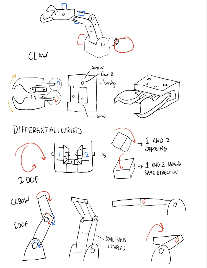
Differential Wrist
One of the most experimental elements of the design was the differential wrist mechanism.
The concept used two servos connected to a shared gear rather than operating as fully independent actuators. The intended benefits were:
- More compact actuator packaging
- Shared loading between the servos
- Reduced moment applied to each individual servo
- Additional redundancy within the wrist assembly
This mechanism allowed me to explore how multiple actuators could contribute to a single wrist system while remaining packaged near the end of the arm.
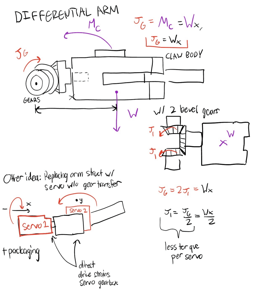
Linkage-Based Claw
I also explored a linkage-based claw intended to distribute gripping forces more evenly.
A typical two-finger claw relies heavily on the fingers themselves as structural members. My concept introduced linkage bars within each finger so that the reaction forces could be distributed across four members.
The intended goals were to:
- Distribute reaction forces through the claw mechanism
- Maintain more consistent gripping force throughout the motion
- Improve structural stability while handling objects
I performed hand calculations to evaluate the proposed linkage arrangement before incorporating the concept into the arm.
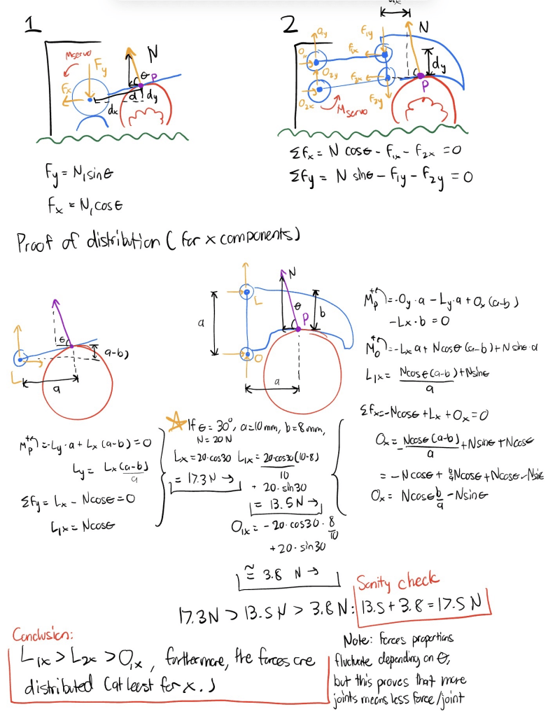
Belt-Driven Arm Layout
The arm was designed around a compact belt-and-pulley arrangement that allowed the forearm motor to remain near the base instead of being mounted farther along the arm.
One pulley was driven by a motor and also carried a second belt. This arrangement created a virtual four-bar mechanism by maintaining tension between the joint and forearm.
The belt system helped:
- Control the forearm’s rotational orientation
- Keep heavier drive components closer to the base
- Reduce the number of pulleys required
- Maintain a relatively compact mechanical layout
A second motor transferred rotation to the lower arm through secured bevel gears.
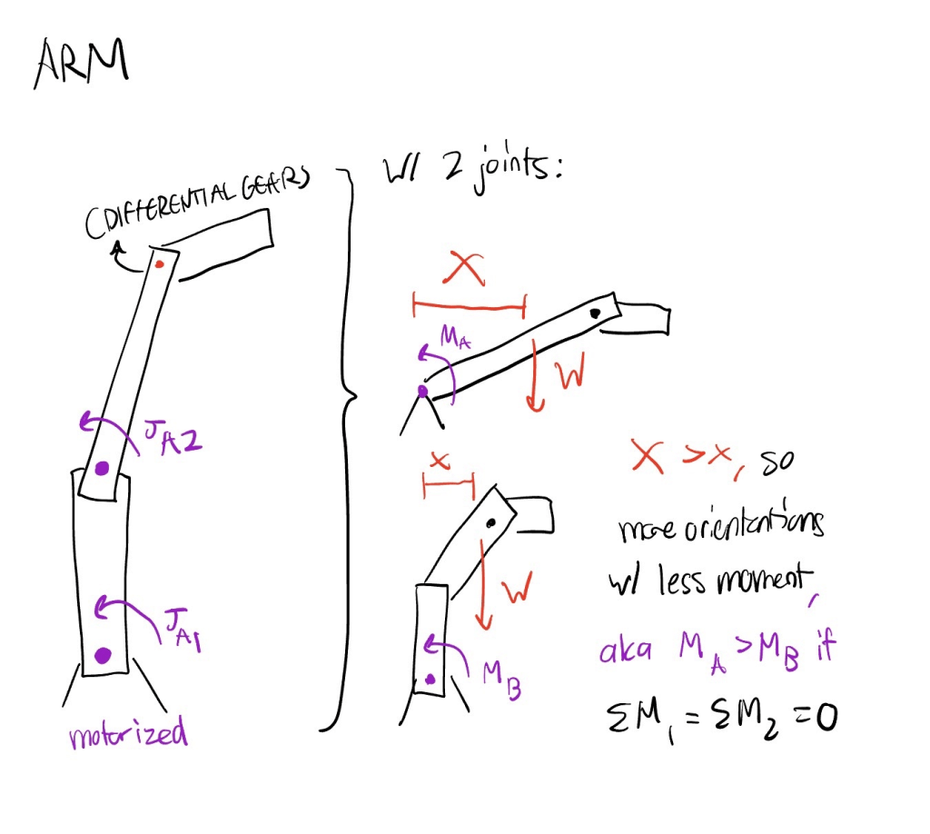
CAD Development
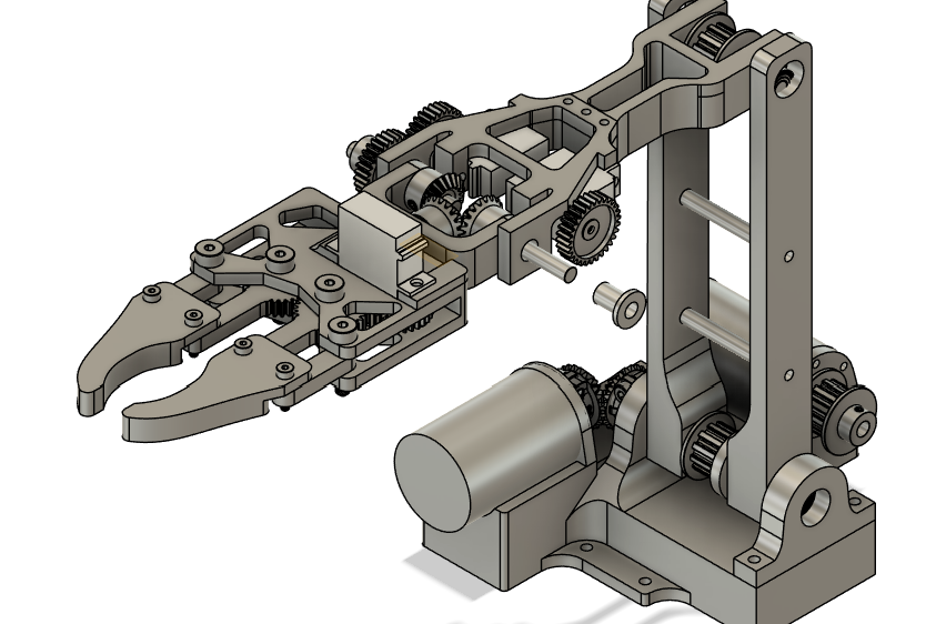
I converted the initial concepts into a complete Fusion 360 assembly.
Key dimensions were defined parametrically so that component spacing and geometry could be revised by updating values rather than manually rebuilding each feature. This became particularly useful while adjusting servo fits, arm dimensions, bearing-block geometry, and pulley spacing.
The first version of the CAD timeline was created quickly and became difficult to modify as the assembly grew. Revising the model taught me the importance of maintaining organized design history and clear parametric relationships, especially in assemblies that require repeated iteration.
Manufacturing and Assembly
Most custom structural components were manufactured from black PLA using a Bambu Lab P1S 3D printer.
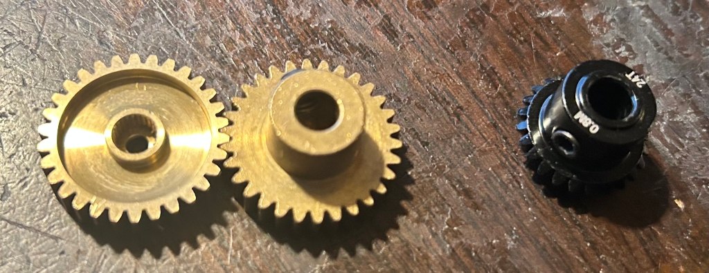
Commercial gears were used for the wrist and bevel-gear assemblies because reproducing their tooth profiles, bores, and set-screw features through 3D printing would have introduced additional manufacturing difficulty.
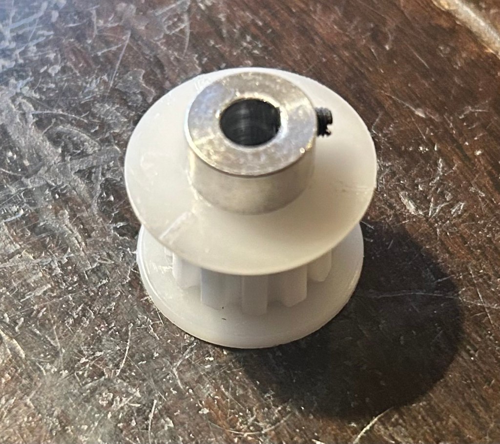
I also selected commercially manufactured McMaster-Carr pulleys and belts to avoid inconsistencies in belt-tooth geometry and printed tolerances.
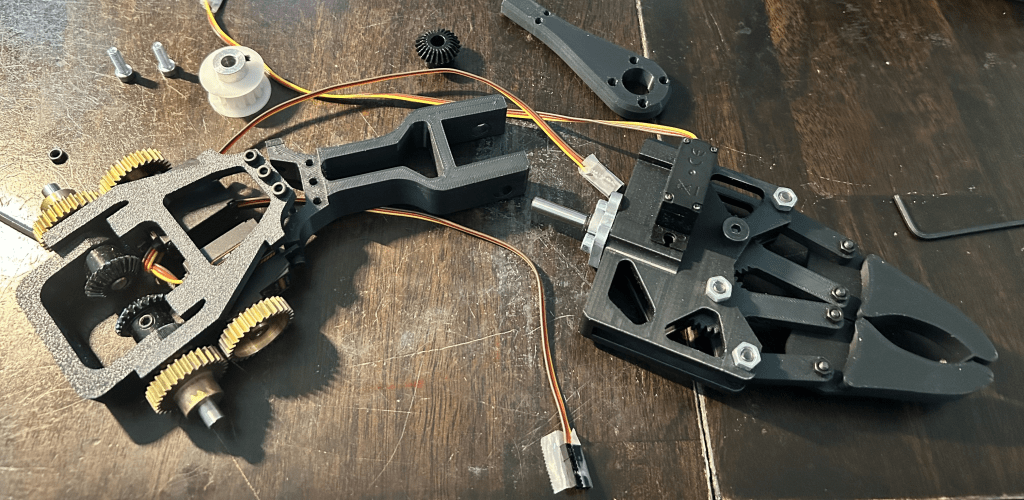
The structural parts were printed using a P1S and black PLA.
Belt-Tension Iteration
The belt system created one of the most significant assembly challenges.
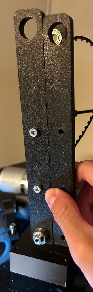
The original pulley center distance was based on a generic online calculator because a manufacturer-specific design calculator was not available. The calculated distance provided only an approximate range and did not fully account for the limited adjustment available in the physical assembly.
The first configuration left excessive slack in the belts, preventing the virtual four-bar mechanism from maintaining sufficient tension. I revised the center-to-center distance through multiple printed iterations until the belts operated more effectively.
This process reinforced the importance of accounting for belt tolerance, tensioning range, and physical adjustment during the initial design stage.
Fit and Tolerance Adjustments
Several printed interfaces were initially either too loose or too tight. These issues affected servo retention, screw installation, and component alignment.
I adjusted the CAD dimensions and reprinted affected components to improve assembly fit. Although this required additional material and fabrication time, it provided practical experience with designing tolerances for fused-filament-fabricated parts.
Design Improvements
Modular Forearm Structure
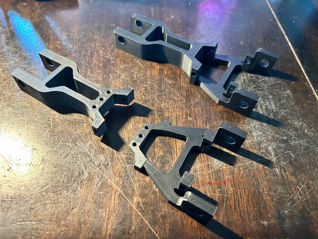
The original forearm was printed as one continuous component. During assembly, I needed to revise the servo fit and shorten the arm to reduce the moment applied to its joints.
Reprinting the entire forearm for every modification would have consumed unnecessary filament and increased iteration time. I therefore separated portions of the structure into smaller replaceable components.
This modular approach made later modifications more efficient and reduced the amount of material required for each design change.
Detachable Bearing Block
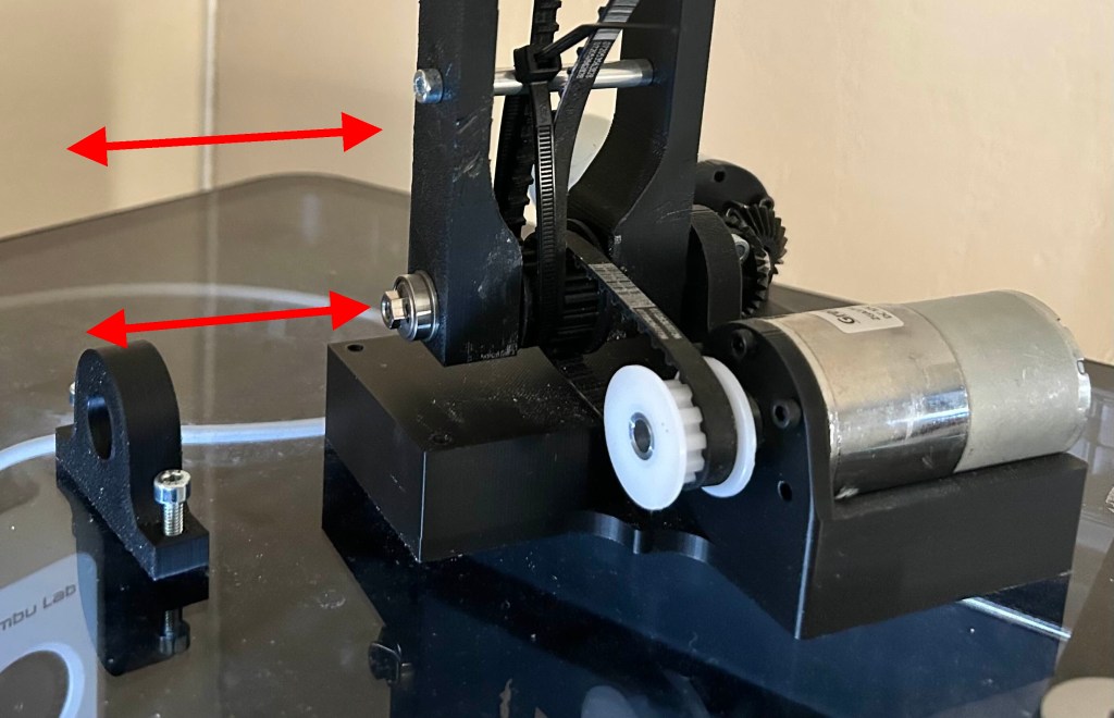
The original design integrated both bearing blocks into the lower rectangular structure. Removing the arm for maintenance required extracting the supporting shaft, which also disturbed several components mounted along that shaft.
I redesigned one bearing block as a detachable component. With the revised configuration, the arm and shaft could slide out together without requiring the surrounding assembly to be fully disassembled.
The modification improved:
- Maintenance access
- Assembly and disassembly
- Component replacement
- Future design iteration
Electronics Development
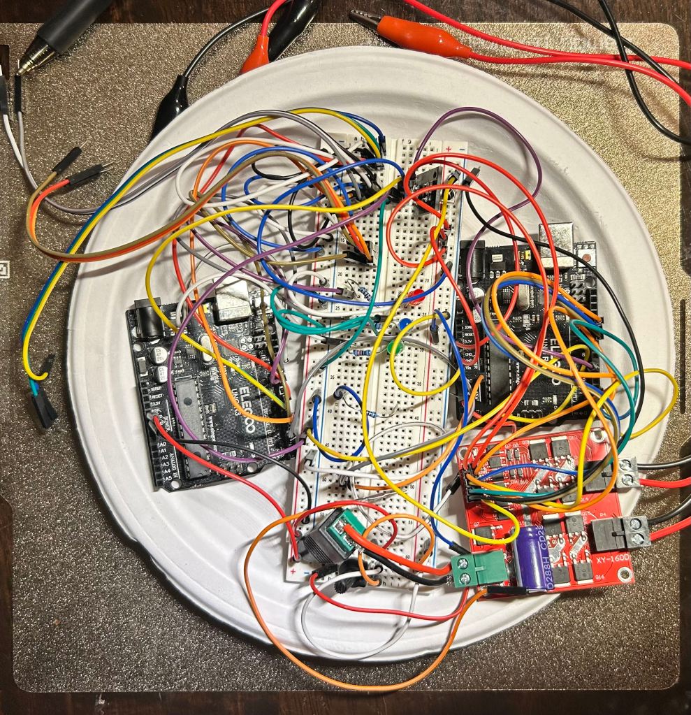
I developed the electronics incrementally, testing one function at a time before combining the systems.
This approach made troubleshooting more manageable because electrical and programming issues could be isolated before additional components were introduced.
- Button and LED prototype
Buttons were first used as inputs, while LEDs provided visual confirmation that the controller was receiving each command.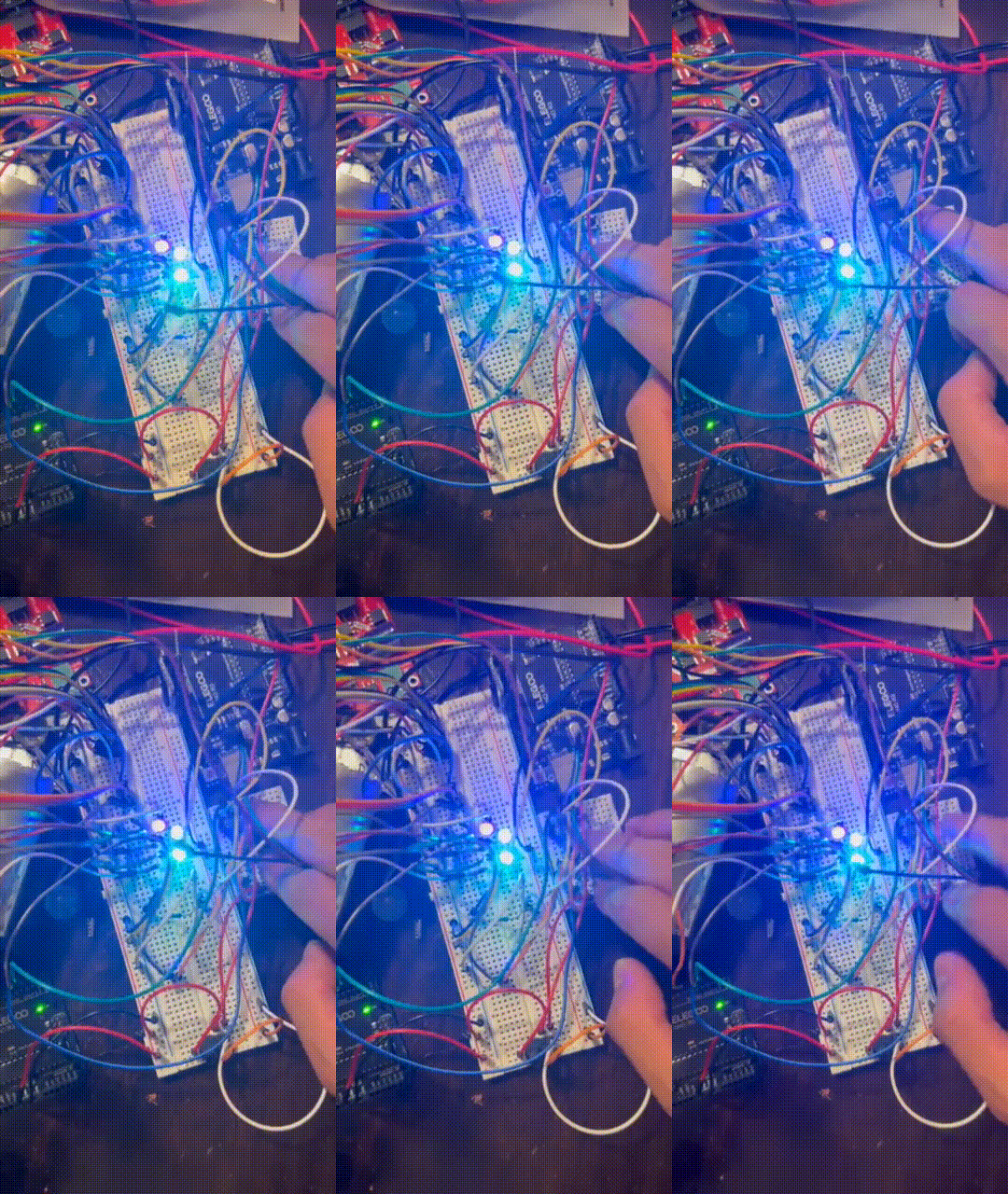
- Potentiometer-controlled servo
A potentiometer was then used to control servo position proportionally. This allowed me to test continuous position input rather than simple on-or-off commands.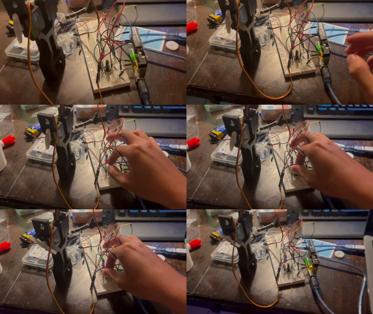
- Button-controlled arm
After the arm was assembled, buttons were used to control the motors and servos directly.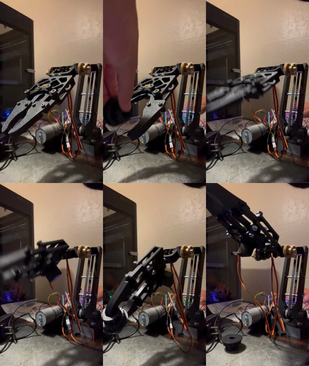
- Infrared remote control
The final iteration used a wireless infrared remote and receiver. This reduced wiring around the input device and made the controller easier to handle independently from the arm.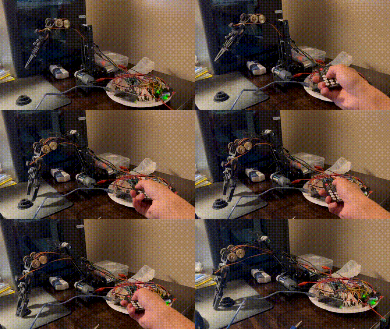
Current-Draw and Stall Considerations
Moving multiple servos simultaneously under load increased current demand and could cause the actuators to stall.
To reduce this risk, I controlled how many actuators could move at once and incorporated rotational limits and position targets into the program. These constraints made the arm’s behavior more predictable and reduced the likelihood of commanding the system beyond its practical operating range.
Programming
The arm was programmed in C++ using the Arduino IDE.
The program primarily translated user inputs into motor and servo commands. Although the project did not use advanced motion-planning algorithms, it required repeated debugging across both software and hardware.
Common troubleshooting tasks included:
- Correcting command sequences
- Revising variable values
- Identifying incorrect circuit connections
- Distinguishing programming problems from electrical problems
- Balancing loop refresh rate with input-control delays
- Defining position targets and rotational limits
- Preventing actuator stalls
Developing and testing each function separately made it easier to identify the source of failures before integrating the complete control system.
Final Outcome
The completed prototype demonstrated a manually controlled four-degree-of-freedom robotic arm integrating:
- Parametric mechanical design
- 3D-printed structural components
- Belt-and-pulley power transmission
- Bevel-gear drive components
- Servo-controlled wrist and claw mechanisms
- Arduino-based motor control
- Wireless infrared user input
The arm remained challenging to operate because each actuator required individual commands. However, the final prototype met the project’s primary objective: creating a functional robotic arm while developing practical experience in CAD, manufacturing, electronics, programming, assembly, and iterative design.
Key Takeaways
This project gave me experience working through the full development cycle of a mechatronic system—from early concepts and hand calculations to CAD, fabrication, wiring, programming, and troubleshooting.
The most important lessons were:
- Build and test complex electrical systems incrementally
- Design assemblies with maintenance and disassembly in mind
- Include adjustment when working with belts and tension-sensitive mechanisms
- Expect multiple tolerance iterations for 3D-printed interfaces
- Use modular components to reduce material use during prototyping
- Maintain an organized parametric CAD model from the beginning
- Treat mechanical, electrical, and software behavior as an integrated system
Although the arm was not designed around advanced automated control, completing it established a foundation for understanding robotic mechanisms and mechatronic system integration.

