SJSU Robotics Club — Mechanical Subteam
Jan 2026 – Present
Project Overview
I was assigned to redesign the SJSU Robotics Club’s rover drive module after the previous configuration presented challenges involving fail-safe operation, motor mounting, structural rigidity, and serviceability.
The objective was to develop a more robust module that could rotate continuously while supporting the rover’s propulsion and steering systems. The redesign also needed to reduce loading on critical motor and shaft connections, simplify motor installation and removal, accommodate a protected limit-switch system, and control the additional weight introduced by the module’s increased complexity.
Design Requirements
The redesigned module needed to:
- Rotate continuously without relying on a slip ring
- Improve structural rigidity under rough-terrain loading
- Reduce cantilever loading on shafts and motor connections
- Simplify propulsion- and steering-motor installation
- Incorporate a limit switch without exposing it to overshoot damage
- Minimize weight while maintaining an acceptable factor of safety
- Use components that could be manufactured through available 3D-printing and machining processes
Design Draft
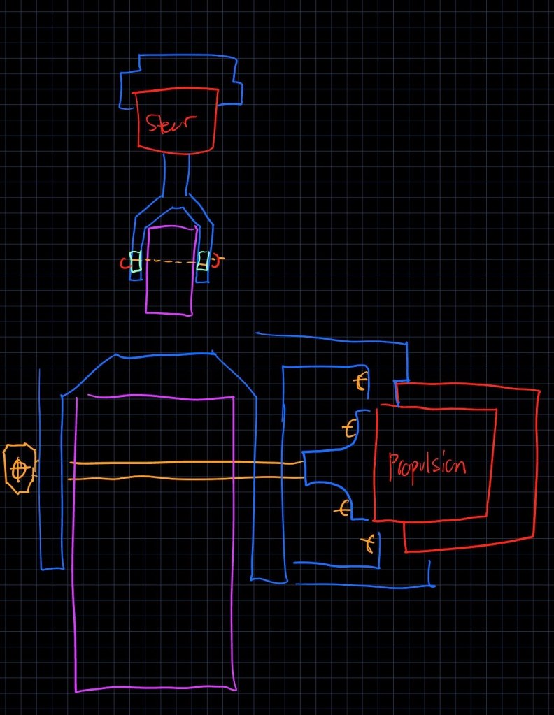
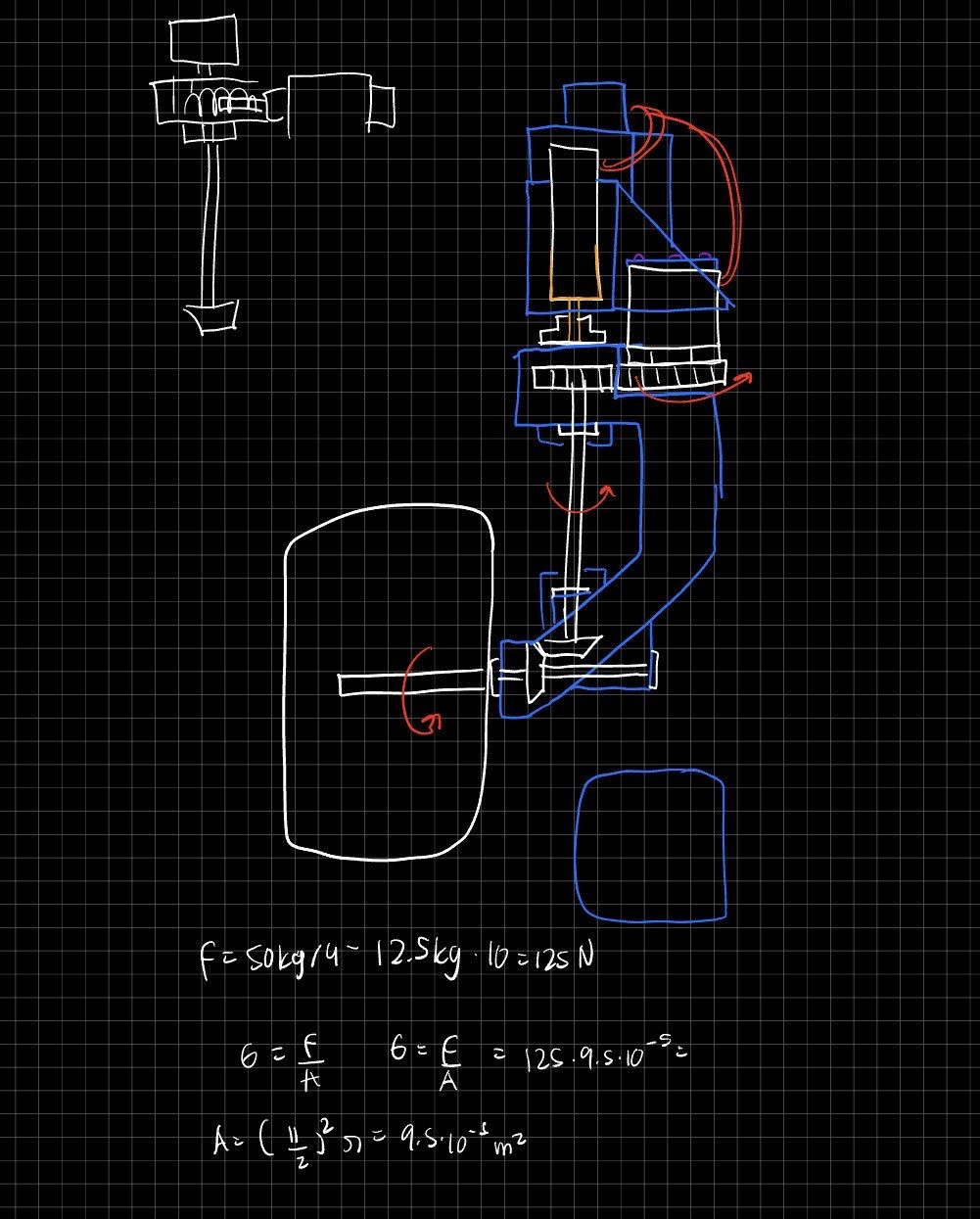
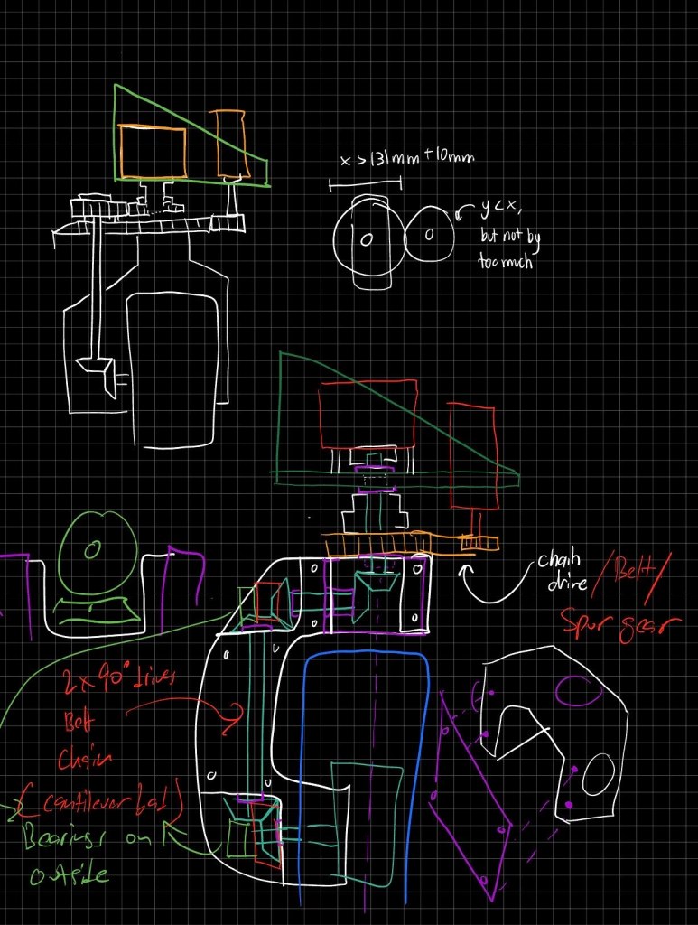
The mechanism progressed through several concept iterations before the final architecture was selected.
Early concepts positioned the propulsion motor so that it rotated with the entire module. Later concepts explored different power-transmission arrangements, including vertically oriented bevel gears and timing belts.
Because limited reference material was available for swerve-style modules at this scale, I relied on repeated concept development to evaluate packaging, shaft support, motor placement, steering transmission, and serviceability.
Designing
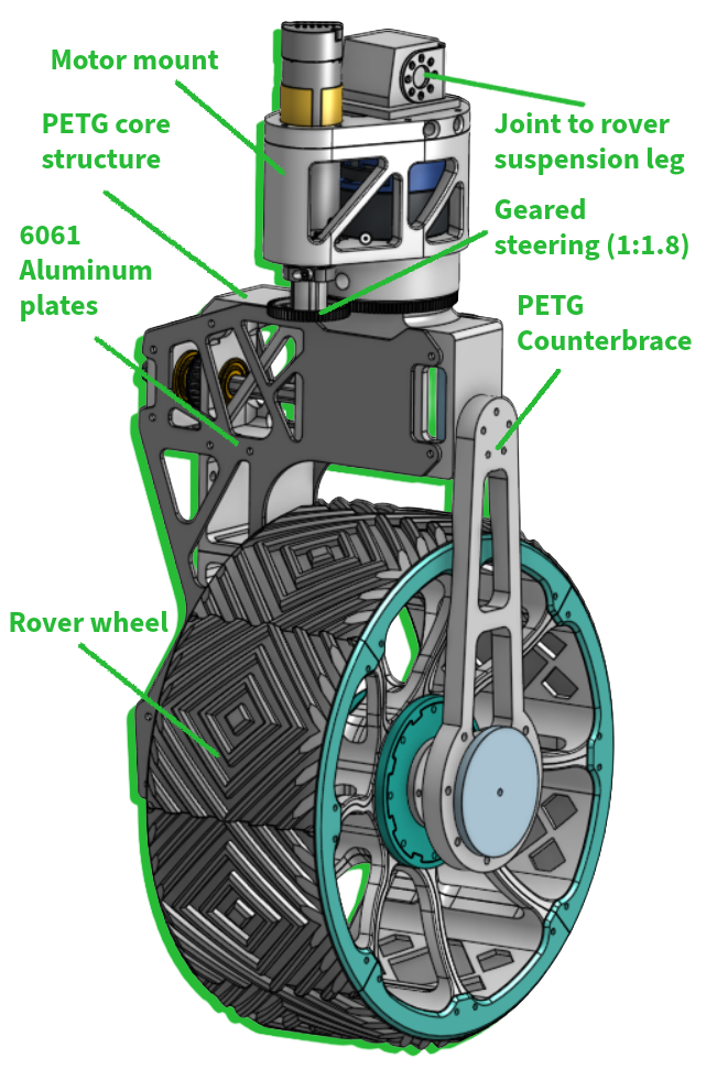
One of the primary concerns was the load applied to the wheel shaft when the rover traveled over uneven terrain.
Because the wheel extended outward from the module, the shaft could behave like a cantilever when subjected to vertical and impact loads. A collision with a large obstacle could further increase bending loads through the wheel, shaft, and supporting structure.
To improve the load path, I added a counter-brace on the opposite side of the wheel. This allowed loads to be supported across both sides of the wheel instead of being reacted primarily through one side of the module.
The brace increased structural support but also added material and weight. To offset this, I incorporated pocketing into the brace plates, center structure, and side plates while preserving material around critical load paths and mounting interfaces.
Propulsion-Motor Interface
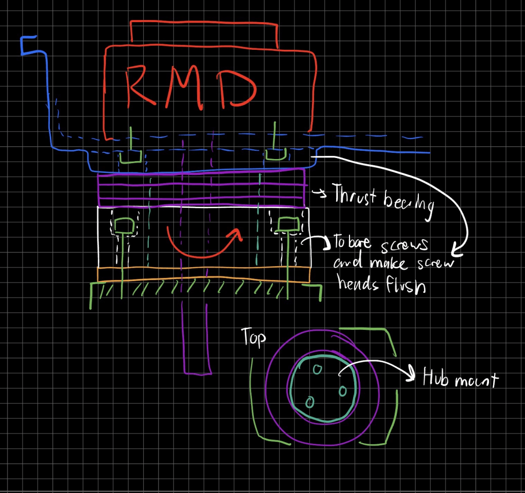
A major design challenge was connecting the pancake-style propulsion motor to the drive module.
The connection needed to match the motor’s mounting pattern while minimizing cantilever loading on the shaft and coupler. An unsupported connection could allow the shaft to deflect or introduce concentrated stress into the coupler.
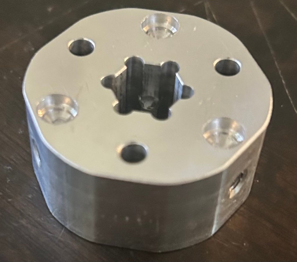
With guidance from club alumni and mentors, I developed a thrust-bearing configuration surrounding the coupler. The bearing provided additional support around the connection, reduced movement at the interface, and helped prevent the coupler from carrying the full reaction load by itself.
The final coupler was manufactured from 6061 aluminum because the component required greater strength than a 3D-printed substitute could reliably provide.
Steering-System Design
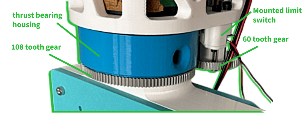
Steering/limit switch configuration
The redesigned module also required a new steering-motor configuration.
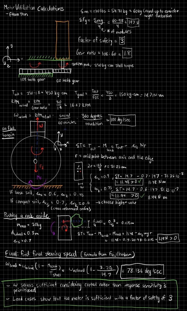
I proposed a goBILDA 30 RPM Yellow Jacket gearmotor and evaluated the configuration using hand calculations based on the expected steering loads.
The steering transmission used a 60:108 gear ratio, equivalent to a 1:1.8 reduction. The reduction increased the torque available to rotate the module, which was important because the redesigned structure introduced additional weight, friction, and rotational resistance.
The steering layout needed to generate sufficient torque under demanding terrain conditions while remaining compact enough to fit within the module’s packaging constraints.
Limit-Switch Integration
A limit switch was incorporated to establish a known steering reference without placing the switch directly in the path of potentially damaging module motion.
The thrust-bearing housing included a small mechanical feature that contacted the limit switch as the module rotated. This configuration allowed the switch to detect the module’s position while keeping the sensitive switch body protected from direct overshoot loads.
The design also left room for a safer fail-state or homing sequence to be implemented through the rover’s control system.
Simulation and Design Optimization
After developing the initial structure, I used Onshape Simulation to evaluate the stress distribution and factor of safety under extreme loading conditions.
The simulation represented the module’s connection to a fixed supporting structure rather than modeling it as freely suspended from the rover’s suspension leg. This assumption was considered when interpreting the results.
Simulation results were used to guide material removal from the center structure, brace plates, and side plates. I hollowed out lower-stress regions while retaining material around shafts, bearings, motor interfaces, fasteners, and other areas critical to the load path.
This process allowed the structure to be refined for lower weight without relying solely on visual judgment.
Prototyping and Manufacturing
The rover needed functional wheel modules for demonstrations before every final component could be machined. To support the schedule, temporary side plates and a motor mount were produced through 3D printing.
These placeholder parts allowed the team to:
- Verify the overall module layout
- Check motor and bearing fit
- Assemble the steering system
- Test the limit-switch mounting concept
- Identify clearance and alignment issues
- Continue rover integration while machined parts were being prepared
The base structure was assembled first, followed by the temporary side plates, steering gearing, bearing components, limit switch, and propulsion-motor interface.
The coupler was machined locally from 6061 aluminum because its strength and dimensional requirements made it unsuitable for use as a long-term printed component.
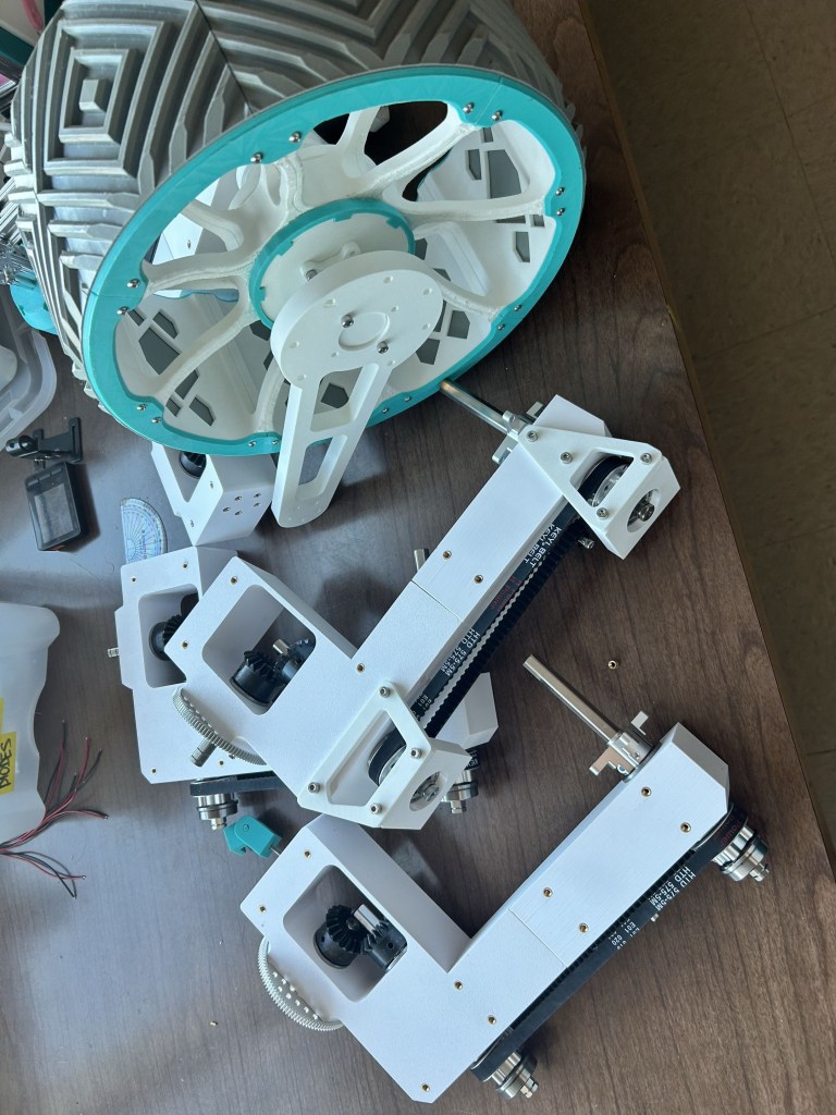
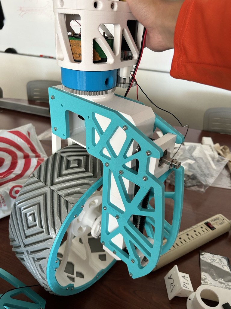
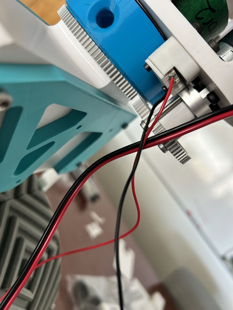
Steer gearing and limit switch mount implementation (The blue part that holds the thrust bearing contains a nub that triggers the switch)
Design Evolution
The module changed substantially from its earliest concepts.
Major developments included:
- Moving away from a configuration in which the propulsion motor rotated with the module
- Revising the power-transmission layout
- Adding support to reduce wheel-shaft cantilever loading
- Supporting the motor coupler with a thrust bearing
- Introducing a geared steering reduction
- Integrating a protected limit-switch trigger
- Pocketing structural components to reduce unnecessary weight
- Using temporary printed components to accelerate integration and fit verification
Each revision addressed a specific issue involving load transfer, packaging, manufacturability, weight, assembly, or serviceability.
Current Outcome
The project produced an assembled drive-module prototype incorporating the primary propulsion, steering, bearing-support, and position-sensing systems.
The design established a more rigid wheel-support structure, a supported propulsion-motor interface, a torque-increasing steering reduction, and a limit-switch configuration protected from direct overshoot loads.
Temporary 3D-printed parts allowed the mechanism to be assembled and integrated while the structural geometry continued to be optimized for final manufacturing.
Key Takeaways
This project strengthened my understanding of how mechanical subsystems must be designed around both structural loads and practical integration requirements.
The most important lessons included:
- Evaluate the complete load path rather than only individual components
- Support shafts and couplers when cantilever loading cannot be avoided
- Use gear reduction to balance motor speed and required torque
- Consider maintenance and motor removal during initial packaging
- Protect sensors and switches from mechanical impact
- Use simulation to guide material removal rather than applying pocketing arbitrarily
- Use temporary prototypes to validate assembly before committing to machined components
- Clearly document simulation assumptions and boundary conditions
- Seek feedback from experienced engineers when evaluating unfamiliar mechanisms
The drive module remains one of my most technically involved projects because it combines mechanism design, structural analysis, motor selection, gearing, bearing support, sensor integration, rapid prototyping, and manufacturability within a tightly constrained assembly.
 Ethan's Portfolio