Supply:
- Greartisan DC 12V 10RPM Gear Motor X2
- DROK DC Motor Driver X1
- Elegoo Uno X2
- IR Remote
- Elegoo IR Receiver
- Miuzei 21G Micro Servo
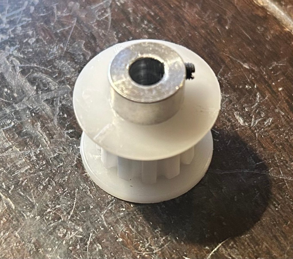
- 2 Mcmaster-Carr Belt Pulleys
- 2 Belts
- Black PLA 3D print filament
Preface
- Over the summer of 2025, I wanted to try creating a robotic arm integrating all of the concepts I’ve learned over my freshmen year of college and look more into electronics. This robotic arm took 2 months of working on and off. Maybe more updates will come in the future… when I’m not too busy.
Objectives
- Create a controllable robot arm that can be moved using user inputs
- Create various ways to control the arm to learn how to configure different input types
- Program the arm to have specific rules and functions to make arm predictable and thus usable
- Be able to utilize generic motors and servos from Amazon (rather than buying from a company I knew about like Gobilda)
- Design and fabricate 3D printed parts that ensures structural integrity against stress and loads
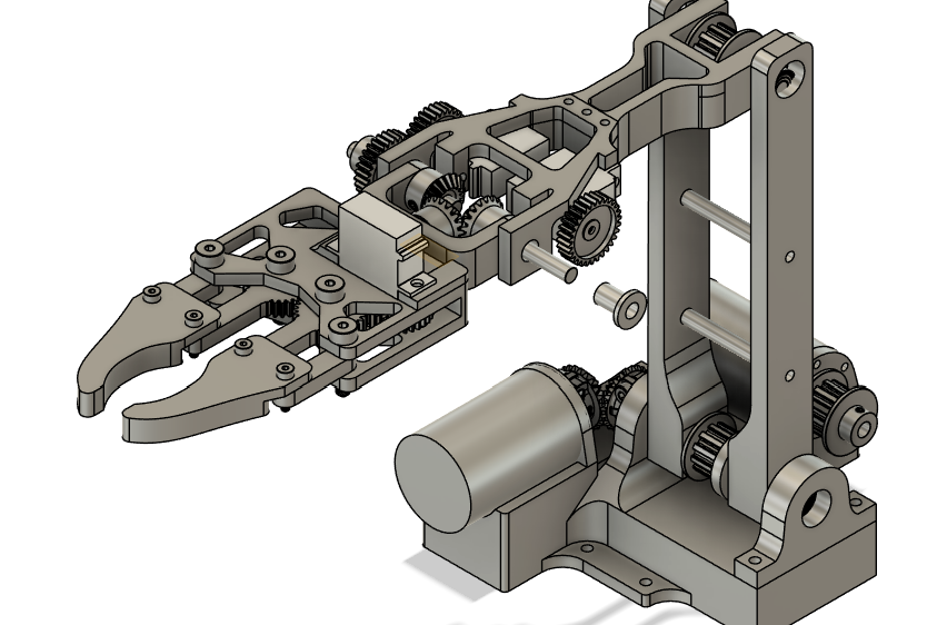
Design Draft
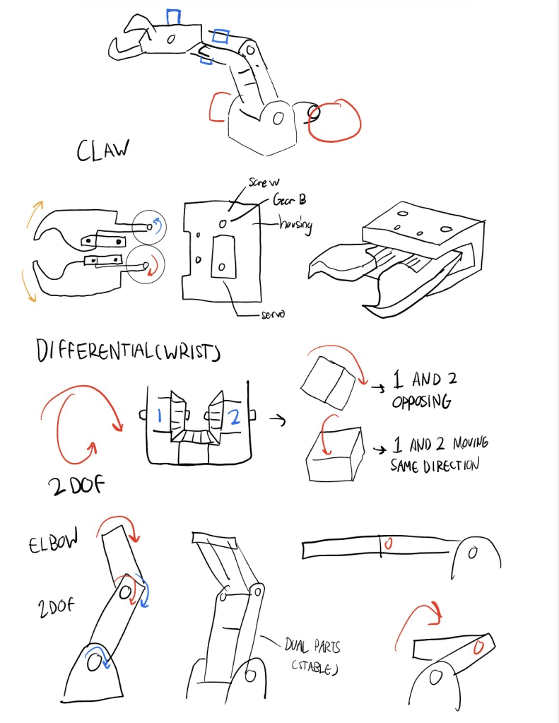
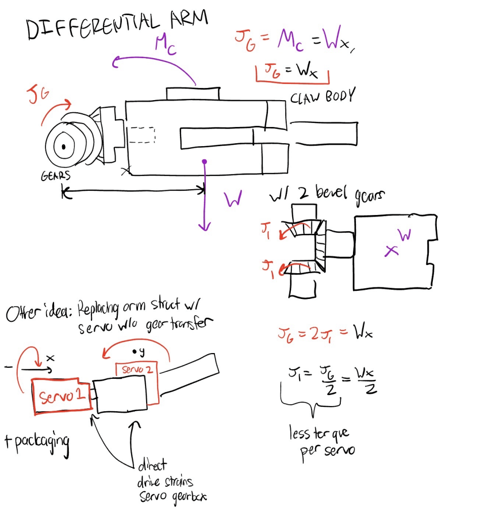
The most experimental mechanism was the differential wrist.
- 2 servos all connect to one gear
- instead of being independent was a concept
- allows for more redundancy as well as less stress on each servo from moment.
- Differential packaging is much more compact
Goal: Create gears that are more stable when picking up objects.
Typical claw : 2 opposing joints and the fingers as the structure.
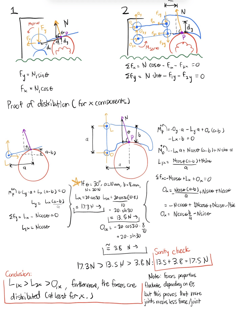
Idea -Create a linkage mechanism within each finger that distributes normal force N from 2 fingers to 4 bars so…
- Reaction forces are distributed
- Maintains gripping strength to be consistent all throughout.
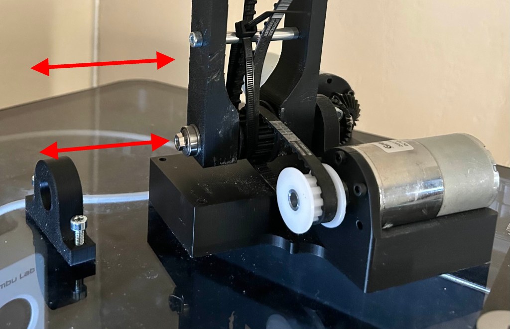
As for the arm itself, I wanted to also create a compact layout through using only 3 pulleys in total to ensure the motor that controls the forearm is mounted at the bottom.
- One of the pulleys is not only connected to a motor from a belt, it also contains another belt that creates a virtual 4 bar mechanism by tensioning on the joint to the robot’s forearm.
- Locks the forearm, and the claw into a rotational orientation. This position is adjustable through spinning the motor.
- The other motor is directly connected to the bottom arm by transferring rotation from secured bevel gears.
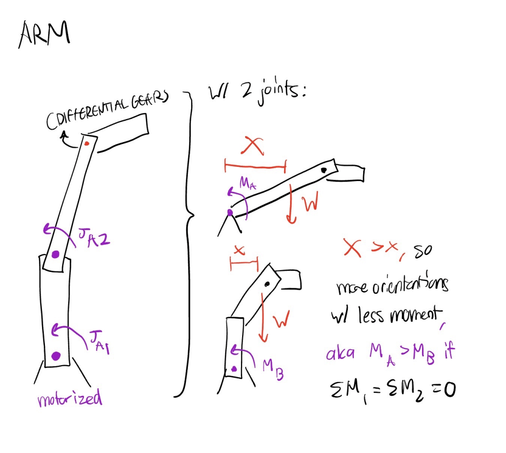
I wanted to give this arm 4 degrees of freedom to maximize flexibility.
With more degrees of freedom, the arm would be flexible for optimal control for driving.
- However, without the use of reverse kinematics, controlling the arm is difficult.
- During this time I wanted to see if I could make a functional arm rather than optimal.
- A prototype that considers reverse kinematics is a consideration, however.
Designing
I then went along with my initial draft to create a modeled prototype in Fusion 360.
To make future changes easier, I made my dimensions parametric. This allowed me to change components of the arm by simply re-inputting a number. I realized that this is best used in collaborative environments because fellow designers may not be as familiar to your timeline compared to shifting parameters.
Admittedly, I made my timeline pretty messy because I wanted to rush a draft to start something, which led to further modification becoming difficult. Had to fix that as I went…
Manufacturing/Assembling It
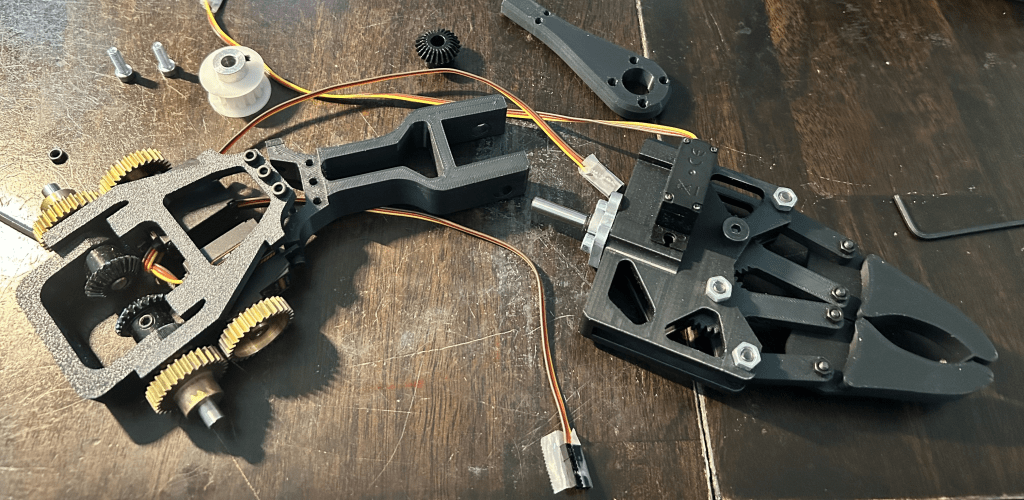
The custom parts were printed using a P1S and black PLA – simple and easy.
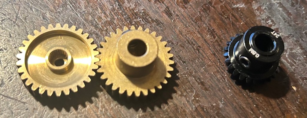
I used Gobilda for the wrist gears and bevel gears because printing it out would be very difficult with the consideration of threads for set screws.
I ordered McMaster Carr pulleys and belts which prevented complications surrounding belt teeth shape and fluctuating tolerances.
The assembly itself turned out fine post construction, however, there was one grievance I had: The belts
The belt length had a considerably low tolerance, since the center to center distance was created in CAD was relative to a generic online calculator since McMaster did not have their own calculator.
It took me some trial and error to get the correct center to center distance, and the process was rather tedious as reprints were abundant.
- Gave a general range rather than one that considers tolerances.
- I assumed that meant the belt would stay tense for a sizeable distance range.
- Pulleys were initially comfortably slacked,
- which made the virtual 4 bar ineffective.
- It took me some trial and error to get the correct center to center distance, and the process was rather tedious as reprints were abundant
I also had to play around with tolerances because some of the fits I had was too loose or too tight, which made installing screws and parts together difficult at times.
Prototypes/Improvements
As I went through the assembly process I had to create some modifications to prevent over complications with reassembling or modifying certain elements on the arm.
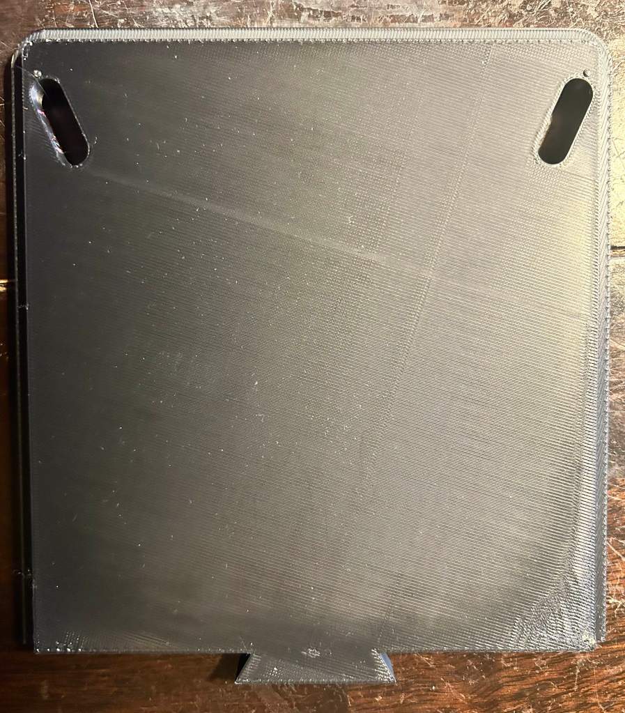
Filament can get costly, so you start wanting to save more. You then start thinking about ways to minimize filament use whenever a modification is needed.
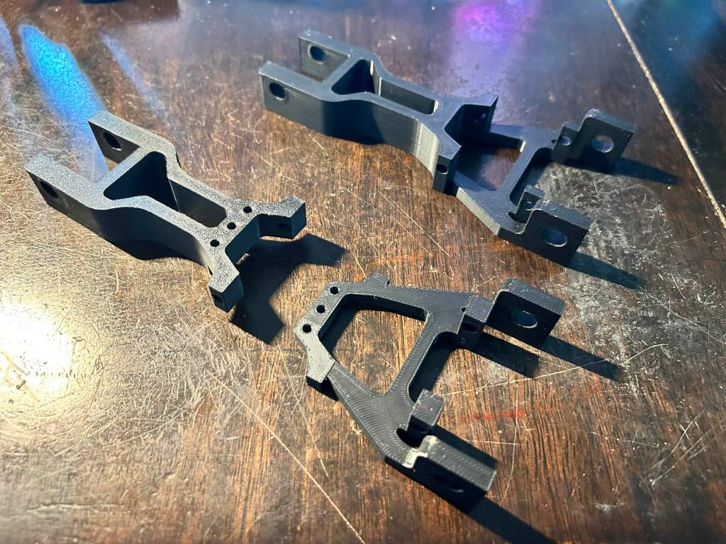
The forearm initially was one solid piece, but i realized i made had to add a lot of modifications and addition, through making the servo fit tolerances tighter to prevent it being too loose, and making the arm shorter to minimize moment on the joints.
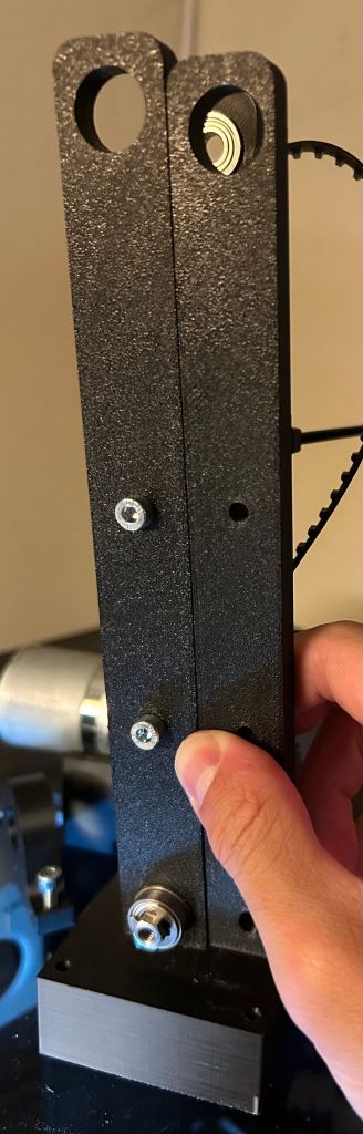
Initially, both of the bearing blocks that held the arm was merged with the rectangular bottom area below it.
- However, removing the arm structure for maintenance or modification was tedious.
- By making one of the blocks detachable, the arm can simply slide off with the shaft it is mounted on instead of needing to slide the shaft, which effectively disassembles the arm because of all of the components mounted on said shaft.
Electronics
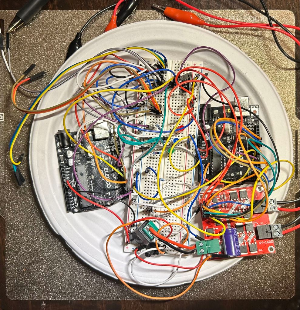
When working on electronics, there is a grit that other components struggle to compete with. Like programming, there is a lot of troubleshooting as you design and create your circuits. A practice I realized made things much easier was to create each important part one at a time and then test each part instead of creating the whole layout and then hoping it works all in one. It makes issues you face much more approachable and easy to find because there are less areas of trouble you have to worry about.
Initially, I created a button prototype that utilized buttons as inputs, using LED lights as physical indicators that the circuit is working while using the Elegoo ONE R3 Controller Board.
Then, as I was assembling I began testing servo movement according to input, beginning with using a potentiometer as the input. This version made the servo positioning proportional to the potentiometer’s position reading.
After arm assembly, I created an iteration that used buttons as the inputs, utilizing the light input circuit but for moving the arm as well. I had to be careful about current draw, as moving too many servos at once and experiencing too much torque would cause stall.
For the current iteration, I switched the input from buttons to a wireless infared controller. This minimizes clustering in the circuit set up as well as making the input item easier to handle as a separate part.
As shown, because each input individually controls a motor, movement is extremely manual and thus makes the arm difficult to operate.
For now, this will be the most current iteration as the goals I had for this project was fulfilled, but I would like to look into this more in the future.
Programming
The programming was done in Arduino’s IDE, using C++. While most of the code I put in was only functions that followed inputs rather than algorithms, I experienced a lot of trial and error.
When debugging, I had to realize whether the issue is an electrical or coding issue. Sometimes the code ran commands in the wrong sequence or declared variables the wrong value, or the circuit was configured wrongly.
Run-time loops also had complications, as I had to balance the refresh rate while keeping a delay for easier control.
All in all, this was a straight forward experience, as I was able to apply my programming knowledge from previous coursework to this project.
